Home
HomeTier 1 Machining of Transmission Components
Background: A Tier 1 automotive machining plant produced approximately 200,000 pieces per day for two large automotive OEM companies. The plant consisted of two departments:
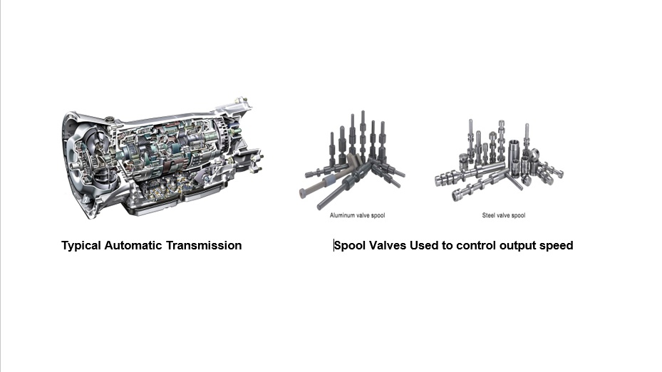
The blanking department which contained 35 screw machines having 8, 6 and 5 spindles. In addition, the shop contained half a dozen single spindle CNC machines and 3 PLC controlled broaches which performed second operation addition of slots and flats and which produced service parts. Aluminum and low carbon steel rod was purchased in bundles and processed on three shifts five days a week into valve spools similar to the above picture on the right. Seventy eight employees worked as machinists and support staff. Part runs were typically 40000 pieces. All screw machines used an oil based coolant.
The grinding department: After the valves were blanked they were anodized (aluminum) or heat treated (low carbon steel). The parts were finish precision ground to a tolerance of plus minus 5 microns on either flow through or in feed centre grinders washed and packed for shipment.
Operational problems: The screw machine shop struggled with the following problems:
Long setup times of more than two days.
Short tool life on machines processing 3% silicon aluminum bar stock. Typical tool life was 3500 pieces between insert failures. Expected tool life for this type of aluminum should have been well over 40000 pieces. For example piston machining processes with 13% silicon aluminum enjoy carbide insert life of over 30000 pieces.
Short tool life on screw machines processing low carbon steel bar stock of less than 1200 pieces. Typical high speed steel insert life of 10000 to 15000 pieces is the norm in automotive OEM engine plants.
1. Long Setup Times:
Situation: Based on an average run of 40000 pieces per run, the shop had five of 35 machines in changeover each day. Setup which should take 8-12 hours was taking up to two days. The long setups were impacting labour efficiency, capacity and throughput negatively.
Analysis: Two reasons were identified as follows:
Cams and gears were stored everywhere; There was no central storeroom for such components. Employees would spend hours looking for what were misplaced or lost components. There were an insufficient number of cams and gears to handle the common feeds and speeds for the majority of setups.
There were shortages of high speed steel inserts, carbide inserts and drills to setup the machine to make each part.
A room off to the side of the machine shop full of junk was cleared and appropriated additional shelving installed.
All setup variables such cams, gears and tool holders were organized and stored by size. A sufficient stock of cams and gears etc were purchased eliminate shortages during setups.
A virtue tool room was setup for cutting tools.
Outcome: Setup times dropped decreased to less than 12 hours. Shortages of cutting tools (inserts and drills) dropped to nil.
Exposure to high moisture environments during transit and storage was not a root cause of the oxidation.
Lack of consistent oiling of the bars at the supplier's mill was the root cause of oxidation of the bar stock.
The supplier contingent asked for a brief period of two months to correct the problem in their process.
Outcome: Approximately six months to the day later, new specially labelled bundles of aluminum bar stock were received. The following benefits were realized:
An almost complete elimination of broken carbide inserts as a failure mode.
Tool life went to multiple 40000 piece runs suggesting that a 95% drop in machine tool downtime would be realized.
Short parts were eliminated.
The operators no longer had to struggle with bundles of bars welded together with oxidation.
The bars out of the opened bundles were oiled consistently over 100% of their surface.
Employees were producing geometrically much more consistent parts and holding tighter tolerances.
The employees had roughly half as much work to do.
With broken inserts and short parts eliminated, the shop also had the opportunity to switch inserts back to high speed steel for a further 50% perishable tooling savings.
3. Short tool life processing low carbon steel bar stock:
Situation: A new high profile Asian automotive OEM customer was attracted, with the opportunity to supply another 25 different transmission components at the rate of 20000 pieces per month of each component. This customer insisted that a computerized gauging system be used to monitor and control part quality and machine up time. This system used three colors to signal the operator: 1. Green - continue to run, 2. Yellow - stop and adjust or change tools, and 3. Red - Stop, parts are out of specification.
During the launch of this product, six machines were needed to inventory up the parts with the first 30 days of production going into a warehouse for the OEM to monitor the timeliness of its new supplier. Within an hour, all six machines were signalling a "Red", stop, condition.
High speed steel un-coated inserts were used in the radial tool holders. Uncoated high speed twist drills were used in all axial drilling locations.
Analysis: According to the leadhand, all six machine tools were down due to an oversize hole diameter in the end of each part. The holes were measuring 300 microns over the maximum specification after making only a few parts. Parts were considered to be within specification on outside diameters. Outside diameter sizing was not as important because all parts were ground to size in the grinding department. Typical hole size was 9 mm diameter by 3 x diameter depth. Further, the hole diameter varied with depth. The holes were wandering off the part axis and exhibited a corkscrew characteristic.
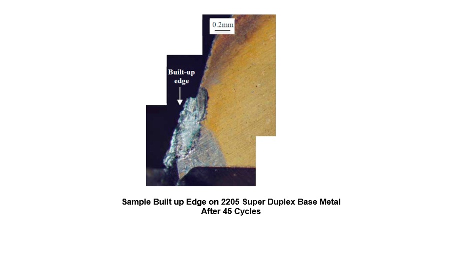
The twist drills were removed from the machine tools and examined under a 40 power microscope. The drills had a thick layer of galling or raw material pickup on the periphery sides of the drill at the tip, consistent with the amount the part bore holes were oversize. Further there was a built-up edge on each cutting edge of the drill.
The raw material galling on the drill periphery sides and cutting edges was a probable cause of the various out of specification conditions.
Lack of positive chip removal from the cutting point may be a second contributory cause.
Action: Coolant fed TIN PVD coated twist drills were procured from a local distributor and installed on one machine.
Outcome:
The multi-spindle machine on which the coolant fed coated drills were installed proceeded to drill over 10000 holes exactly on size (9 mm). At around 12000 pieces the drill still produced diameters within specification but the hole had started to wander off the axis of the part indicating the tool was starting to get dull.
Subsequently other identical drills of varying sizes were procured and installed on the other 5 machine tools. Within a few days, all six machine tools were producing parts in the "Green" on the computerize SPC inspectionsystem.
There was a 90% reduction in downtime associated with twist drill tooling changes.
With the machines now running, a few weeks later an inspection of the radially cut surfaces was conducted. These features of the spool valves exhibited under magnification a very rough cut surface consistent with a cutting tooling which was plowing rather than cutting. An examination of the un-coated high speed wire electric discharge machined cutting inserts found a large built up edge on every insert.
A sample of TIN coated radial cutting inserts was obtained and installed on one machine tool.
Outcome:
Part size variation was reduced by 90%.
Insert life increased from an average of 1500 pieces to over 10000 pieces.
Visual quality under magnification revealed a surface finish consistent with that of an almost ground part.
There was an 85% reduction in machine tool downtime for radial insert cutting tool changes.
Throughput and employee productivity increased by 40%.
Final Notes: A factorial study was not conducted to assess the dominant root cause of the impact of both variables (TIN coating and coolant fed). It was presumed that both were important. The TIN coating presents a very smooth lubricious coating which delays the formation of any built up edge or galling defect. The coolant flushes the chips and keeps the drill edges cool also delaying built up edge formation and delaying wear, maximizing life. In this business, long tool life is paramount to good part quality and low cost.
The picture below is a sample of built up edge on a twist drill.