Seven Wastes Case Examples
The following examples are given:
 Mercury marine video (Muda in high gear) - this is a classic example of waste.
Aluminum Jobbing Foundry sand casting process (material handling, inventory, waiting, rework, over processing, over production)
Rework or scrap (Rework in pump factory assembly, piston casting scrap)
Waiting (line balance problem in Tier 1 fuel assembly)
Service Business quote processing time (waiting)
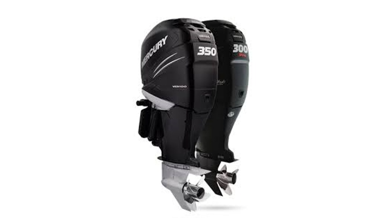
1. Mercury Marine: This video which is now over 25 years old is a classic example of waste in a multi plant multi department process used to make a key part for an outboard motor. It shows the process of making the transom spanning over six months where 99% of the time there is no value being added.
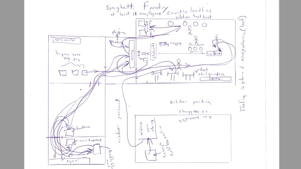
2. Sand Foundry Example: An automated moulding machine in an aluminum jobbing foundry was making aluminum castings for over 200 different customers. The foundry was quoting a lead time of six months and part prices which were 30-40% above the market. Internal casting or process scrap was as high as 80% on some products. After watching the Mercury Marine video and reading a couple of books on the Toyota Production System, Burns Bridge sketched the process flow shown below on a piece of paper.
The sketch, created in five minutes shows the actual torturous path, of materials through a foundry site consisting of three buildings and 60000 thousand square feet.
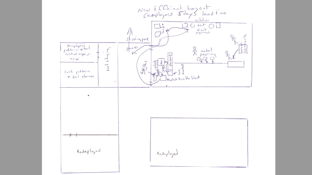
The revised version of this layout is shown below. All of the operations required to make a casting from core making to heat treat are now located in one building. It took less than two months to create this layout. A number of other improvements were accomplished through the same period and later as follows:
Locked pattern and tool storage area created (see sketch below.
Networked order entry system installed with customers, products, processes and respective tools added. Pick lists generated daily.
Two solution heat treat furnaces removed and sold.
Natural gas heaters were added to maintain solution heat treat quench water at temperature around the clock. This eliminated quench cracks from cold water.
The heat treat recipe times were cut by 70%.
At least 10000 square feet of factory space was freed up for other uses.
A program of simple tool process conversions was initiated to convert 1. the majority of hot box cores to the quick setup, high speed cold box Laempe process and 2. low speed high skill jolt squeeze match plates to high speed low skill automatic moulding.
The order lead time including order entry through to packing including heat treat was reduced to five days (one calendar week) from 6 months.
All downstream processes were now clocked by the automatic moulding machine, encouraging supervision and employees to work to the clock cycle of the moulding machine. This raised productivity on all processes in the cell.
Approximately 3 lift truck drivers were no longer needed.
A total of seven other employees were no longer needed.
Moulding productivity on matchplate conversions went from 16 moulds to 120 moulds per hour.
Core making productivity increased 300% with each hot box conversion to high speed cold box.
Bottlenecks in the three melting furnaces combustion air piping were addressed increased there melting capacity by 300%.
Two melting furnaces in the manual jolt squeeze department were surplus and sold.
Casting quality increased quickly now that defects were found within minutes of the mould being poured in contrast to months later in the old process.
This layout change drove a sea change improvement in casting quality from defect levels as high as 80% to under 8% consistently.
This layout was also key in increasing the foundry annual capacity from 1 million to 2 million pounds per year.
3. Rework and Scrap Examples: The goal in any modern business process quite simply should be zero defects. The reality is that many organizations struggle along with significant levels of scrap and rework at every step of their process. Tragically some organizations who are not able to address their scrap problems pride themselves in their ability to manage it by working overtime having lots of meetings and deciding little, charting the problem to death and a host of other non-productive items. Some very large multinationals fall into this trap.
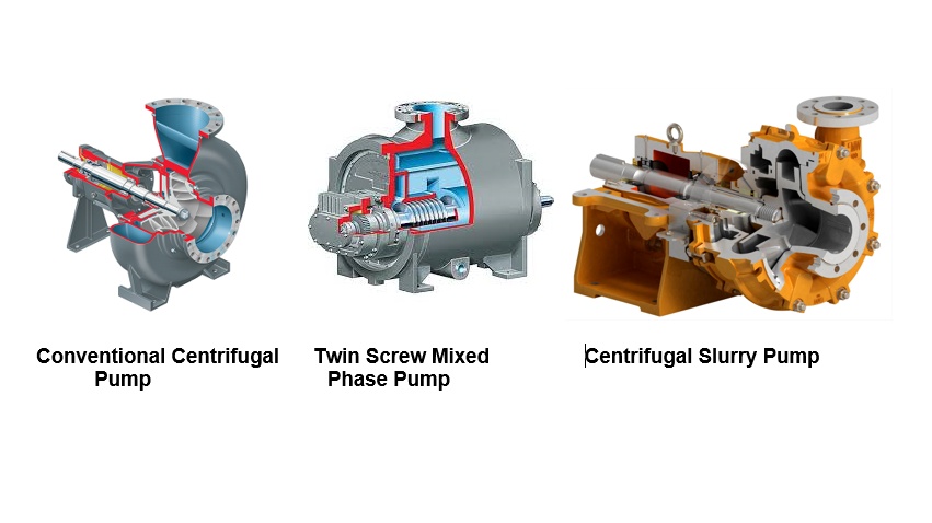
Example 1 - Engineered pump manufacturing plant: A plant in south central Ontario produced centrifugal (water and slurry) and PD (gear and twin screw) pumps for international customers. It had an official reported cost of quality (internal scrap, returns and warranty) of 6-7%. As with any quality system, the onus of reporting by diligently completing non-conformance reports is such that typically less than half of the waste is actually reported.
For example in this shop when the assembly and test supervisor was asked for his ideas on how to improve assembly and test stand productivity, his suggestions were terse: 1. build the pump once and 2. test the pumps once. The reality in this department was that all pumps were being assembled at least twice, 1/3 of the time, thrice and a few pumps several times. The test stand had a similar metric. There were a host of internal problems with broken mechanical seals. None of this was included in the reported cost of quality for the site. Thus the real waste was at least double the reported number.
While much effort can be expended to make the recording of internal and external waste more accurate, this itself is waste. Better for management to admit the true extent of the problem and focus their efforts on waste mitigation and the improved reporting of waste.
In addition to the quality issues, the plant's on time metrics were very poor (35% for pumps and 55% for parts). From hearsay these problems had existed for the life of the plant (about 40 years).
Examples of the product being manufactured are shown below.
The following are a few examples of the problems which were identified and corrected:
Hard face plasma arc welding coating of screws cracking (rework): A review of the procedure reconfirmed the need to provide a preheated element to 600F. Actual practice was below 300F due broken electrical resistance heaters. Heaters were repaired and the proper preheat was established. The employee was retrained on the importance of maintaining preheat. All re-machining and re-welding rework was eliminated.
Worn out CNC machine tools: The shop had approximately 30 CNC and manual machine tools, non of which had seen any maintenance in over 25 years. An overhaul campaign was conducted to address all issues. Two examples are given here. Two vertical turret lathes one CNC and one manual both cut with substantial taper. The bridges were adjusted to eliminate the taper. This removed all skill from operation of both machines, made them much less stressful for the machinists to run and increased their productivity to the point where one person could run both machine tools. Impellers were bored and faced on a three axis vertical CNC mill and then parabolic profiled on a horizontal CNC lathe. After machining the machinist de-burred the parts and then passed them on to the balance cell where they were dynamically balanced. Both machine tools had an average slop of over 0.030" on each axis. The shaft bores on the impellers which require a plus minus tolerance of 0.0005" were oval, cork screwed and of very rough surface finish. Proper inspection if it had been completed on each impeller would have rejected every one. Employees were passing on bad quality without reporting it (because it had been going on for years). Spindle rpms were below 400. Both machine tools were over hauled to bring runout and play back to less than 0.001" on each axis. The following benefits were reaped: 1. Spindle speeds on the mill were increased to 1600 rpm, with 2. bore size quality improving to easily exceed the tolerance and 3. surface finish was mirror image quality. The lathe experienced a similar improvement. Productivity in the cell improved to the point that machining and balance could be combined into one cell . The equipment was rearranged to combine balance and machining into a combined work cell. This saved two employees (one on each shift) for a savings of 140000 p.a. Fit quality problems between the impeller and shaft were eliminated.
Poor doweling: Alignment of a pump is a KPI (key product indicator). Pump design can be divided into two broad categories 1. spigoted (alignment is controlled by machined spigots on mating components) and doweled assemblies where alignment is dialed in by the assembler and dowel holes subsequently drilled and pins inserted after assembly. Dowel holes were crooked, oval and had parting face steps. In some cases dowel pins were specified too small and in other cases they were missing from the drawings. Dial indicators were being used. The manual dial indicators process was prone to errors. A new digital alignment kit which had been purchased was not being used. To address this, assemblers were trained on an appropriate standard acceptable dowel hole quality. They were also trained on how to detect dial indicator droop and adjust for it in their alignment work. An inventory of good quality sharp drills and reamers were purchased and inventoried in the toolrom. A small portable radial drill was purchased to facilitate in assembly doweling of smaller pumps. A decision was made on larger units to have the doweling done on the larger three axis horizontal boring mills. With these improvements alignment issues from spigoted pumps were eliminated. This also eliminated one family of mechanical seal failures. A training class was arranged with the vendor to train shop assemblers on how to use the precision digital alignment gauge. Within three months, use of this instrument was so popular, that employees asked for the purchase of a second alignment tool.
Mechanical seal failures on horizontal suction top center discharge style pumps: Assembly was experiencing apparently random seal failures during the build of this family of pumps (8 different frame sizes estimated). These were spigoted assemblies where the operator has no control over alignment and bolts everything together. A KPI quality check was implemented to have the employee build the pump without the seal and sweep the stuffing box with a dial indicator to verify that eccentricity is less than 0.003". Subsequent to this, it was found that at four frame sizes had concentricity issues of more than 0.020". A mechanical seal will break if misalignment is more than 0.010". A search for the root cause eventually found play in the second operation of the machining fixture used to machine the bearing cartridge on the CNC vertical turret lathe. These fixtures were pad welded and turned to dial the pads within 0.001" of the bearing frame OD machine in operation one. This resulted in concentric bearing frame cartridges and eliminated a whole family of mechanical seal failures.
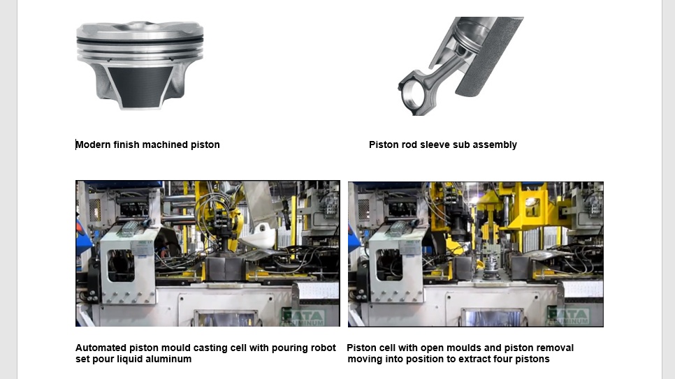
Example 2 - OEM Piston Casting Cell (circa mid 1990's): The above graphic shows a modern automotive engine piston together with a typical rod sub-assembly. An automated permanent mould casting process is shown at two points in its process, just before the metal is poured and just before the piston castings are extracted from the moulds. Automotive engine designs are highly optimized with the objective of increasing fuel economy and increasing the fuel to weight ratio. Engine speeds and compression pressures are rising to increase the power output and energy efficiency. Accordingly component manufacture has evolved at a similar pace to add a high level of automation and ever increasing productivity.
In this case example, an automotive OEM piston casting cell similar in design to the above had a casting scrap rate of over 16% in a process where 4.5% or less would be an accepted maximum. The cell had a total of 8 casting machines staffed by four operators per shift (12 total) and two dial cutoff machines staffed by two operators per shift (six total). In addition, 2 tool general setters looked after mould cleaning and preparation and management of tool changes on the cutoff machines. A large cross fired regenerative melting furnace melted pigs of aluminum. The furnace was tapped into a ladle for ladle transport of the aluminum to two gas fired holding furnaces having two bailout wells each.
The cell was struggling to produce 6000 pistons per day and in spite of overtime on weekends, the assembly line had to purchase pistons weekly from a sister engine plant to satisfy the demand of 12000 per six days per week.
Eight to ten skilled trades were dedicated to process maintenance (1 millwright, 1 welder, 1 electrician, 2 machine repair, 3 tool & die makers, 1 pipe fitter).
Four three axis mechanical arms using precision proportional hydraulics poured the metal alternatively into each of two double mould piston casting machines.
After some investigation the following opportunities were identified:
The cutoff machines were experiencing a high cost of durable tooling of $250000 per year (budget 25k)
Cutting tool life (trepan station) was less than 500 pieces (250 machine cycles between insert changes). Inserts consumption was five times the expected level for this process.
Type 1 visual inspection errors meant that good pistons were being scrapped.
Furnace maintenance was averaging $250000 per year when it was believed that $50000 would be more reasonable.
The pistons after cutoff had shrinkage cavities at the rate of about 10% at the base of the risers. More of these defects were being found after finish turning in the final machining process.
On the one cutoff machine, pistons were falling off the chucks into the chip conveyor before automatic extraction (lost product).
The pistons after cutoff had unacceptable levels of eccentricity averaging a six sigma of 0.120". This was resulting in non-clean up defects found after finish turning.
The pistons tops contained sub-surface blisters which could not be seen until after finish machining and coating.
New mould coatings would come off on the first pour forcing the operator to clean and reapply the coating wasting at least one hour at each mould changeover.

2. Trepan station insert life: After fixing the clamping issues with both dials, it was observed that insert life on the trepan station was not consistent with insert life yoyoing between 500 and 1600 pieces. To save money the tooling engineer was having the dog bone shaped carbide inserts ground twice. In the storage cabinet at the machining centers were three different inserts in the drawer in blister packs labeled new, regrind 1 and regrind 2. The operators changing the inserts did not know the importance of installing three of a kind on the spindle tool holders. As a result the three inserts were cutting in different planes and only one of the three was doing the cutting.
A detailed procedure was written on how to change the inserts and verify that they were set to cut in the same plane with dial indicators. Storage of the inserts was improved to insure there was no mixing and matching going forward. Employees were trained.
Outcome: There was another overall improvement in insert lifer from 1000 to over 1600 pieces between changes. Machine tool up time improved to over 75% with another improvement in throughput and drop in consumable tooling.
3. Type 1 inspection errors: After final cutoff parts were visually inspected and packed. The employees did not have any visual standards and in their interest of doing a good job were highly conservative. A lot of good pistons were being scrapped. A type 1 error is defined as "part is good but inspection process declares it bad".
To resolve this problem a set of visual standards (pictures of pistons with defects) were procured from a sister American plant and entered into the shops QS9000 quality documentation. A one day training session was conducted with every visual inspector. Actual piston samples were collected similar to each picture.
Outcome: There was a 95% reduction in type 1 error scrap. Errors were still made but at a much lower frequency.
4. Excessive furnace refractory repair maintenance costs: A review of the furnace repair specifications found that the OEM was having the furnace relined when all that was necessary was melt line oxide chipping removal and reapplication of the affected areas with suitable crack patch refractory compounds. The work scopes were rewritten to specify repair rather than replacement. The vendors recommendations were included to further reduce cost.
Outcome: Annual melting and holding furnace repair costs dropped to $25000 per year from $250000.
5. Piston ring land shrinkage casting scrap: Ten to fifteen percent of the castings being produced were being scrapped at cutoff due to surface defects in the ring land areas of the pistons. This was a nose bleed level of discount.
After investigation it was believed that the water cooled moulds were running too slow. A central US casting plant was running an identical piston casting process at a 58 second cycle. The Canadian process was running at a 74 second cycle. The casting machines were hydraulically operated and controlled by programmable logic controllers. The automatic ladles were also hydraulically controlled using Parker proportional hydraulic spool valves on each of three axes. The valves were controlled by PLC's with PID output cards.
There were many motion faults associated with the proportional hydraulics. This interrupted the smooth operation of the casting machines and resulted in more cold moulds and cold parts being produced. The engineer who had programmed the equipment indicated that he had to slow down the process (add more time) to minimize motion faults. As a result the machines were running 20% slower than a much larger sister piston casting cell in the USA.
Burns Bridge's suspected that this was an oversize valve (valve sizing problem) and after analyzing the stroke speeds confirmed that less than 10% of each valve capacity was being used. New smaller valves were installed on each axes and the motions returned.
When fine tuning was complete and with other fine adjustments made to operator controlled parameters, the cycle time was reduced to 64 seconds from 76. A hand held optical pyrometer purchased to help troubleshoot this problem indicated that the moulds were now running at an appropriate temperature.
There was a second problem with backlash in the rotary actuators which could not be eliminated. At the business end of the ladle six feet away this was resulting in positioning variation of almost an inch which was resulting in a lot of spilled hot liquid aluminum. In spite of very high quality stainless steel mesh armoured water cooling hoses, the operation was plagued with water leaks and unsafe liquid metal explosions from the moulds. There were small stalactites of aluminum on the roof deck 50 feet above the casting machines as evidence of the problem.
To solve this problem at the suggestion of one of the employees simple pins and bushings were made from hardened low alloy 4140 tool steel. The pin was installed on the casting machine and the bushing on the ladle. When the ladle squatted to pour the metal, alignment was controlled to within 0.010". Spilled metal and damaged water hoses were eliminated as was any downtime associated with repair and replacement of the hoses. A major safety problem was eliminated.
Outcome: Casting deck productivity more than doubled to 15000 pistons per day from 6000. The plant no longer had to import half its pistons from a bigger US casting plant to meet the daily engine assembly requirements (12000 pistons per day).
There were three other issues fixed on the casting deck each of which contributed to further improvement as follows:
Changeover mould coating adhesion.
Mould close sensors.
Run machines continuously.
The following problems were identified:
Repair coordinator knowledge - the repair coordinators were inexperienced and had no knowledge of the product for which they were responsible for preparing quotes.
Cleaning of pump components after disassembly and prior to inspection was problematic. It was taking weeks for outside vendors to strip tungsten carbide coatings.
The document system was disorganized.
An error prone paper system was used.
Repair coordinator training: The repair coordinators were immediately asked to attend daily lunch and learn training sessions conducted by the site manager and the repair engineer who had 25 years subject matter experience. Subsequently, the coordinators received training on mechanical seals, torque, non destructive testing, couplings and alignment as well as other related topics. Each coordinator was scheduled to attend engineering training sessions at a 3rd party in Pennsylvania and a second week of training at an OEM plant in Oregon. ERP SAP quote module training was also provided. A the end of seven months, these coordinators were assessed as being in the top 10 percentile of repair coordinators within the corporation.
Tungsten Carbide removal: One of the repair coordinators was asked to head a problem solving team consisting of a shot media supplier, a shot blast cleaning services company representative, and the manager for an internal HVOF tungsten carbide coating process. In less than two weeks a solution was obtained which reduced the time to strip and clean castings by 95% and also cutting the cost of the service by more than half.
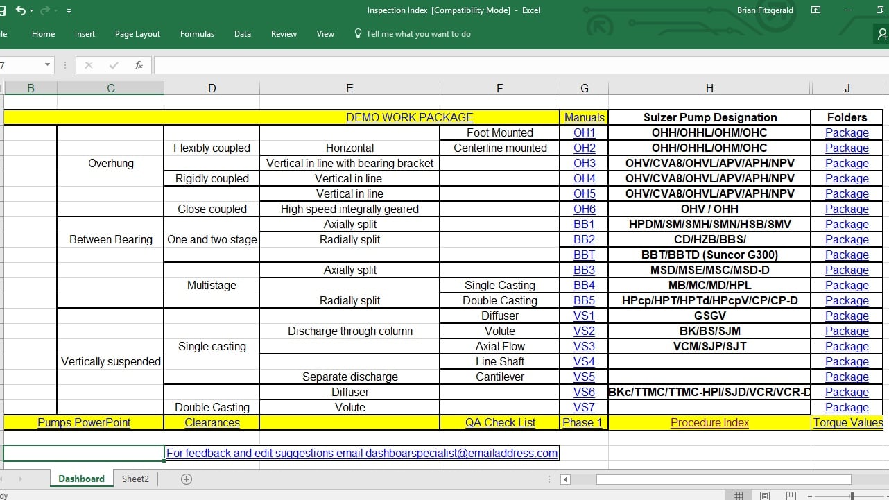
Messy Document System: The site's document system consisted of approximately 300 documents with arcane names stored in one computer system directory. It took a long time to find the correct forms. Often the wrong forms were used. In lieu of finding a form, an inspector would create a hand written one. To address this issue repair forms were solicited from three other large repair centers and added to the internal library. These forms were then sorted by type of pump and stored in pump specific document directories. Using a spreadsheet, a dashboard containing numerous hyperlinks was created. An image of this is shown below. With this new dashboard added, a set of project repair documents for a new job could be created by anyone with network access in a few keystrokes.
4. Error prone paper system: Paper forms were printed and then completed by hand. This introduced many errors and omissions to the process. A decision was made to go to a paperless shop and two laptops were purchased and installed in the shop. Inspectors were taught how to find the correct job, open the appropriate forms and enter content from visual and dimensional inspection of the components. An assortment of errors were eliminated.
Outcome: The time required to prepare a quote dropped to an average of 20 days. Further, quoting errors were reduced by over 90%. Morale improved drastically as work was received and the shop started to move toward a defect free operation both on the floor and in the office. Cost of quality dropped from 25-30% of sales to less than 1% in 9 months. On time delivery improved from 0 to 75% through the same period.
Closing Comments: Waste is everywhere in an organization. It can exist in business processes as much as out on the shop floor. A good continuous improvement program should look for opportunities to reduce waste everywhere within the organization.
