Quick die change - setup reduction examples
Background: Traditional inventory management taught that there was an economic order quantity which increased with the setup time. This was often called the economic batch quantity. However with the implementation of Japanese manufacturing techniques (Toyota Production System), called in the west Lean Manufacturing. it was recognized that as the setup cost approached zero, the economic batch size became one unit. This is popularly known as "one piece flow".  Shigeo Shingo's book, A Revolution in Manufacturing; The SMED System describes in detail the process of setup time reduction. While the book primarily deals with setup related to large stamping processes at Toyota, the concepts can be applied to any business and technical process.
Setup processes are redesigned to convert as much of the internal setup as possible to external setup. This optimization results in an ever shorter internal setup time.
The following case examples are detailed here:
Glass bottle plant changeovers
Glass bottle plant mould shop
Aluminum foundry order entry system and pattern tool shop
Tier 1 fuel bundle fabrication plant new tooling changeover specifications
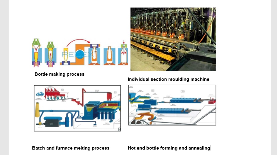
Background: In the 1980's, a bottle plant with 12 production lines, melting and moulding approximately 600 tons of raw materials per day to make a wide variety of liquor wine and food containers for the southern Ontario market was running with 16-18% downtime (not including job changes) and a very poor quality pack rate of 50 to 60%. The plant averaged 20 job changes per week or an average of three per day. The plant was a 7 day 24 hours operation that only shut down for statutory holidays and a 2 week summer shutdown to perform major maintenance. Furnace rebuilds were done every 7-8 years. The plant had 1200 employees and staff. With the high downtime and low pack rate plant financial metrics were an unqualified mess.
Analysis:
With job changes being handled on three shifts the changes were not going well with an average job never reaching the standard pack.
Production runs were taking twice as long as needed, due to the long ramp up times associated with a job change and the associated poor pack rates.
Tooling for each changeover (moulds, blanks, hangars, delivery troughs etc.) was arriving late onto the floor or not at all with machines down waiting for tooling from the mould shop (located in the basement)
Tooling was being manhandled on 4 wheel pushcarts. Due to restrictions in the hot end at one furnace tooling had to be hand carried up to 50 feet to and from the individual section (IS) machines. This was an ergonomics issue which was causing unnecessary delays.
Setup sheets were not well documented.
The temperature control instruments were not accurate and drifting by degrees per day in a process where setup gob temperatures must be repeated within 5F from run to run (a six month gap) and be held to +_0.5F during the run.
The annealing tunnel ovens (lehrs) which stress relieved the bottles and cooled the glass down to room temperature were not holding set points when empty. The tunnel interiors would cool down and would take six or more hours to warm back to operating temperature. This resulted in the culling of glass for poor stress relieving which was otherwise ready to pack.
Specialized changeover crews were set up headed by two supervisors working two days on and two days off, 10 hour shifts from 7 am to 5 pm 7 days per weeks. These crews would remove the iron from the previous job, clean the machine and hang the new iron. At the same time the fore hearth gob feeder would be changed over with cams and and an orifice. As soon as possible during the iron change, the feeder would be started gobbing to allow the fore hearth temperatures to stabilize to steady state to the correct gob temperature from the setup card.
Four senior employees skilled in the setup of IS machines with timing drums were promoted to the position of bottle specialist and given a higher rate of pay. These employees were responsible for the final adjustment and fine tuning of the machines to produce a good bottle.
The mould shop was assigned the objective to have all tooling needed for a job change on the production floor three days in advance. (See the next case example). A new manager was assigned to the mould repair shop to ensure this metric was achieved.
A narrow aisle lift truck was purchased to replace the hand trucks previously used to move the tooling from the staging area to each machine. A staging area on the production floor with sufficient space was created to facilitate the staging of up to 10 different jobs (20 steel pallets). Ergonomic forkable stands were purchased. The purpose of the stands was to present the tooling pallets at an ergonomic height at the front and rear of each machine for tooling coming off and then tooling going on. This minimized heavy bending and lifting of moulds by employees.
A control was put in place to vet any proposed changes to job setup sheets to avoid any corruption of the information or loss of data and to also ensure that the information was complete.
Finally the following improvements were made to the temperature control instrumentation:
Outcome: There was a wholesale improvement in job changes which took place over a nine month period where the plant transitioned to a daily process where all three job changes were packing by 4pm each day 85% of the time.
The improvements to the instrumentation measuring gob opticals and controlling the forehearths resulted in instruments with zero drift after even six months. This meant that a gob optical from a year ago could be reproduced in the process with 90 minutes of starting to run the feeder.
Cleaning of glass mould tooling coming off the machines.
Cleaning of variables tooling (gob delivery chutes and guides)
Inspection of damaged and repaired tooling.
Welding and repair of tooling.
Storage of tooling (housekeeping).
Paper files.
Action Items:
Dirty moulds and blanks were being cleaned in a large heated 2% acid water solution soaking tank having suspended basket conveyor. Extra labour was required to run this machine. It was large (30 feet long by 12 feet wide) and consumed large amounts of electric power to run the resistance heaters. This machine was replaced by a small shot blast machine having a 3 foot rotating table that used specialized glass bead and ran on a 2 minute cycle. This machine was installed in the shift mould repair shop up on the production floor. Underutilized shift mould repair employees were used to clean all the tooling coming off the machines for free. This resulted in an annual labour savings of four employees. The old mould cleaning machine was removed to scrap, freeing up valuable storage space in the machine repair maintenance shop.
A Typhoon pressure washer with a 60" table was purchased for the variables shop to achieve similar benefits.
Two employees were responsible for inspecting all mould tooling coming off the floor and all tooling going back for job changes. This meant that two employees had to inspect 40 sets of tooling a week or one set of tooling every 4 hours. Each set of tooling contained typically 24 moulds and 24 blanks plus neck rings, blow heads, bottom plates etc. all of which had to be inspected for damaged. The mould repair process involved the following steps: clean, inspect, powder weld repair, duplicator lathe turn, bench grind, inspect. The inspector's work scope was reduced to off coming inspection only, eliminating them as a bottleneck. The powder weld seam repair, bench grind bench was shifted to the middle of the shop. After tooling had been re-profiled on the duplicating lathes, bench repair employees would then perform any remaining spot powder welding repairs to seams and bodies and perform final inspection. By performing their own inspection, these employees became more accountable. Ergonomic stands were purchased to present the pallets at 30" height to eliminate bending pick and place stress. The employees lifted the tooling off the pallets onto their work bench and completed any simple needed weld and bench grind repairs. Inspection was completed by the employee doing the repair in a fraction of the time and without any material handling and delay to move the tooling to a second inspection station.
Previously one employee welded and a second employee did the bench grinding finishing work. With the new location of the work table, each employee did their own hand held torch powder welding and bench grinding.
Storage of tooling: The shop was a mess with over 90 pallets of tooling sitting on the floor in the aisles between the storage racks. The plant stored an inventory of over 200 sets of tooling which involved at least 400 pallets of iron. A room in the rear of the shop was full of obsolete open drip proof electric motors of 1940's vintage. The shop had received authorization to scrap over 100 sets of tooling but had never scrapped anything. The motors were scrapped along with the primitive associated racking. New racking was purchased and installed. A senior employee was assigned to sort through the 100 sets of obsolete tooling with a view to keeping anything that could be reused elsewhere. After completion of these items, the shop now had over 90 open storage locations. No more tooling was stored on the floor for an obvious improvement in shop safety.
Paper files: The plant had been in operation for almost 70 years. In the mould shop not one piece of paper had been thrown out. There were three job change meetings per week. Attending these meetings required the manager and the shop supervisor both to carry a two foot high heavy stack of paper files to the conference room. An employee who had dropped a mould on his foot was offered "light duty" to sort through the files and retain the last version of each document, e.g. packing slip, revision drawing, revision proposal etc. After four weeks the number of filing cabinets had been reduced from 10 to 3 allowing one person to now comfortably carry the files to the change meetings. Staff could now find key documents much quicker.
Outcome: These changes were implemented over a period of six months. Halfway through this process, the central mould repair shop started to meet the three day metric 90% of the time. Incidences of late tooling arriving the day of the change were virtually eliminated. The plant went on to achieve and surpass its job change lost time metric of 4%.
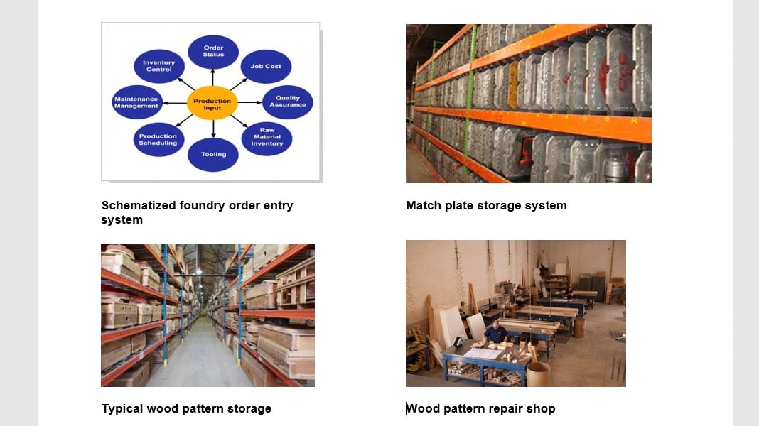
2. Foundry order entry system and pattern and tool storage and repair shop:
Background: An aluminum foundry in the 1990's was quoting six month lead times at a time when there was excess capacity and casting prices were dropping. The market expectations for delivery quality and supply timing had markedly shifted to an environment where weak players were going bankrupt. The foundry produced 1000 different castings in sand permanent mould and high pressure die cast for 300 different customers. The market expectations for quoted delivery were now 6 weeks or less. The above graphics show key elements of foundry order entry and pattern and tool storage and repair.
Analysis:
The foundry had no computerized order entry system. It was taking more than six weeks just to prepare an order for production. There was no database which included such things as customers, products, pricing, processes, factory routings or tooling etc. An error prone paper system was used.
There was no formal pattern and tool repair shop. Nor was there a proper system for storing patterns and tools. Tooling was stored everywhere and in haphazard fashion. For example an order received from a customer might require a small core box the size of a lunch box or smaller. Often, nobody knew where it was. Often it would take another six weeks of searching to find all of the tooling.
A rudimentary small business order entry (ERP) management system was purchased and modified to run on a small IBM personal computer network having four desktops.
At the same time, a central location in the shop was selected for the pattern and repair shop. The hot box core making shop which had been obsoleted by core box conversions to a high speed cold box process was selected for this purpose. A second room to its rear which had also been obsoleted due to other process conversions was cleared. Roof penetrations were repaired capped and sealed. Overhead door and man door gaskets were installed to seal against winter heat loss. Windows were removed and replaced with cinder blocks, again to facilitate loss of heat through broken glass. One ceiling level gas heater was repaired and reactivated in the new repair shop. All manual machine tools and scatteredwood pattern repair equipment including work benches were relocated to the new location. A chain link fence was installed with a padlocked gate. A key was given to each employee who worked there with the instruction to keep the shop locked when they were absent. The setup of the repair and storage areas took less than two months.
The tool room and ERP system was initially loaded with the 100 highest volume running tools, As new orders were received, the tooling was found and stored in the tool room and the related product and customer information entered to the order entry system.
A young engineer with leadership skills was hired to manage and plan the affairs of the shop. Within a few months, this individual had created a one month backlog of tooling conversions and repairs for the three pattern and tool repair employees.
Daily pick lists of tooling needed for production were generated and issued to the floor for unskilled employees to pick and deliver to a variety of work stations.
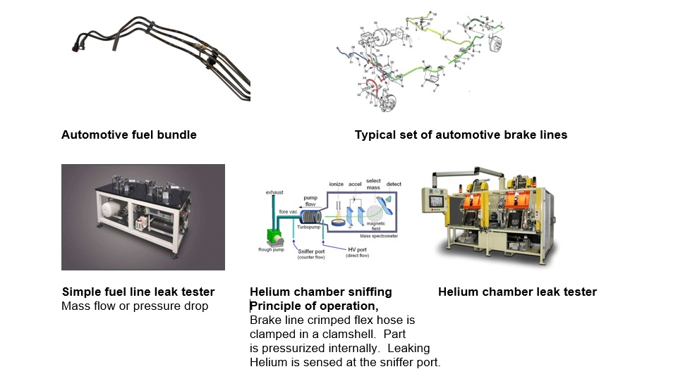
4. Fuel and brake tube bundle leak testing equipment best practice specifications:
Background: A small engineering team of 13 in an automotive plant needed to improve productivity drastically during a perfect period of financial storm in the early 2000's. The plant had 350 employees on a 5 day 3 ship rotation with the bulk of production on day shift. Raw tubing was purchased, cut, end formed, bent, crimped inserted and leak tested.
The engineering team for each model year change over, would bread board a layout for a new more productive production final assembly cell which included the following processes bending, crimping, insertion, leak test and final assembly (add plastic clips) with the objective of achieving a 35% improvement in productivity. The performance criteria, were, "0" defects, 100% on time delivery of all project deliverables (prototypes, production part approval process part submissions, work cell documentation, run at rates, launch parts and production part deliveries).
Analysis: Given that the final assembly bottleneck was leak testing much of the improvement focus was placed on the leak testing process. Engineering staff had poor knowledge of how the leak testers worked. The leak tester speeds were typically 30 cycles per hour and experienced a high first time through test failure rate as high as 70%. Final assembly work cells had equipment spaced apart which resulted in unnecessary material handling of parts from process to process. Procurement of dedicated benders and leak testing equipment from local equipment 3rd party vendors was a time consuming problem riddled process with many visits to the sub vendors.
The leak testers were initiated with palm buttons which unfortunately led to pinching type injuries as supervisors added a second employee to improve productivity. There were a host of minor issues which each leak tester with which employees had to struggle with.
Action Items:
All engineering and quality staff were trained on how all leak test sensors worked (pressure drop, mass flow, and mass spectrometry sniffing).
An intensive focus was made to eliminate the root causes of poor first time through test success.
Best practice specifications were created. As improvements were made to the leak testers, these documents were continually amended to incorporate the latest knowledge gained from each cell launch.
Light curtains were installed on all leak testers to eliminate the pinching injuries. Guard removal limit devices were installed on all dedicated benders to prevent employees from removing guards.
All of the minor issues which employees struggled with on each leak test cycle were assessed and eliminated with technical fixes one by one.
The root causes of first time through test failure were found and eliminated with technical fixes which were added as amendments to the best practice documents.
Final Comments: Setup reduction is more than just how quickly a process may be changed over. The above examples demonstrate a wide spectrum of process setup reduction initiatives, each of which had a profound impact on organizational performance.
