Burns Bridge Engineering 


  • External link opens in new tab or windowHome
  • About Us
  • Services
  • Lean Manufacturing
  • Leadership
  • External link opens in new tab or windowValue Proposition
Burns Bridge Engineering
Menu
    • External link opens in new tab or window
    • External link opens in new tab or window
  • External link opens in new tab or window
    • External link opens in new tab or window
    • External link opens in new tab or window
  • External link opens in new tab or window
  • External link opens in new tab or window

Automotive Tier 1 Stamping Shop - Bottleneck Easement Press Shop  Examples


Situation: A stamping and welding plant consisting of 150000 square feet, 350 employees had a number of internal throughput bottlenecks which resulted in a delivery record of 97%.  In automotive tier 1 manufacturing; the expected minimum metric is 99.99%.  The plant was incurring $70000 per month in premium freight.


 The plant contained 10 side frame presses ranging in size from 400 to 2000 tons.  The majority of the presses were coil end fed but could be configured differently based on the product.  The welding shop contained 50 robots with 25 performing mig welding  and 25 units spot welding.


The plant suffered from the following problems:

  1. Press shop up time of 18-25%.  A well running press shop will run at 85 to 90% up time.

  2. Excessively long change over times of up to two days.  Keeping in mind that some shops change their presses in minutes,  a 4 hour changeover for this shop would be considered acceptable.

  3. An epidemic of smashed stamping dies which resulted in a tool room running chronically 100% over budget. 

  4. Weld shop rework in excess of 60% in an industry where 2% on a bad day is considered acceptable.


Analysis Press Shop: At the suggestion of the senior maintenance millwright, a die protection program was undertaken.  Every press was already outfitted with an electronic press control which was only being used as a counter.  A selection of key employees, engineers, tool and die makers, managers and an electrician were sent to a one day course to hear a die protection specialist discuss the ends and outs of die protection and press control.  The expert advised that employees should tackle the most difficult problems first.

On return to the shop, the two worst problematic dies were selected which had never run well (usually failing within the first 25 strokes.

Case 1:  A two on 800 ton press die was selected having aerial cams on a pressure plate.  The stampings were approximately 10" x 16" of depth 4", 16 gauge.  The sides were angled at about 45 degrees.  One 2" hole was punched on the one side.  The punches were located on the upper ram on a stripper plate.  Cams drove the punches forward at a 45 degree angle after the stripper plate made contact with the strip.  Gas air springs were installed to assist the physical cams with retraction.  In one of the later sections clinch nuts were pressed into each stamping.  The clinch nuts strings were not adequately supported and broke frequently.  The die had a history of running for only a few strokes before crashing.  This die was considered the worst performing and highest maintenance unit in the shop.

Step 1: An end of strip sensor was installed first.  An end of strip sensor is an inductive proximity sensor installed at the discharge end of the press.  If the strip does not progress and is not detected by the sensor, the ram stops 15 degrees or so before bottom dead center.  An un-progressed strip means that the strip is probably folded over in the die doubling the thickness in a cavity where only one ply is allowed.  This prevents severe catastrophic damage to the die and avoids locking of the press at bottom dead centre.

 Almost immediately the press stopped.  Upon investigation the tool makers found a slug from the blanking station under the folded strip.  A new longer punch was installed which ensured proper ejection  of  the slug through the bottom half of the die set.

Step 2:  Within the next dozen cycles the die was smashed with broken aerial punches together with the matching die windows ripped out of the bottom half of the die.  Staff wanted to erroneously blame the operator.  Visual inspection of the strip confirmed that the punches before breaking had successfully punched holes in the stampings indicating the the breakage happened after the ram passed dead center and was opening.  The only way that such a failure could occur is for the punches to not retract in the die.  It is not possible for a press operator to see such a condition in a closed die set and therefore stop the press.

The die was opened in the tool room and the stripper plate retraction assembly design was inspected.  Backlash of 3/16" was observed in the mechanical cams.  The punches retracted were recessed by only 1/32" in the stripper plate.  This meant that the punches could stick by one eighth inch in the bottom half of the die.  Due to this backlash the die design dependedon the gas springs for full retraction.  Gas springs are not a robust way to retract punches due to presence of burrs which can drastically increase the force needed for retraction.

The root cause was deemed to be design and the tool was returned to the vendor to be corrected.  Upon return to the press shop with the punch retraction fixed and with further knowledge of the operation of the stripper plate and aerial cams and punches, two additional inductive proximity sensors were added to accurately, prove the seating of the stripper plate a few degrees before the ram reached bottom dead center.  A mechanical teeter totter was used to amplify the motion for the proximity sensor to achieve the resolution needed to protect the aerial punches and windows.

Step 3:  To address the issue of broken nut strings, special feeder brackets were constructed and mounted on the ram to support the strings and feed the nuts into the die.  The feeder brackets eliminated the feeding swaying stresses and the bending of the nut strings at the clinch nut drivers.

The die proceeded to run without incident.

Outcome: The use of end of strip sensors became standard process in the shop.

Case 2 Situation: Another 2 on stamping die with angled cams on the ram die was suffering severe cam damage after only 25 strokes.  The die was making a class II stamping for a tailgate corner of an automotive truck (a class II stamping is a component not visible to the end purchaser).  An end of strip sensor was installed with no improvement in die life.  It was concluded that this was not a die protection problem.     


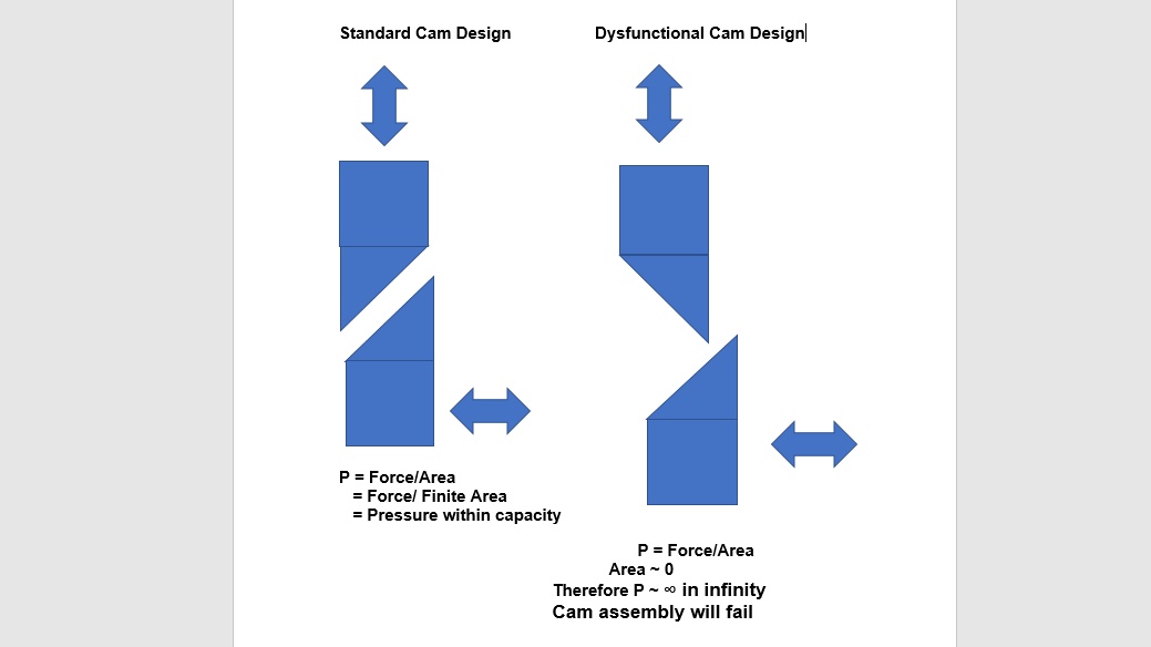
Case 2 Analysis: The die was opened in the tool room and the cam design reviewed. The above sketch, left hand view, shows a properly designed cam set. The problem tool possessed cams as per the right hand arrangement. With the upper cam backwards a point contact area is created having an extremely small effective area of action constructively creating an infinite stress at the point of contact. With this arrangement the cam set would fail after a few dozen strokes. This was a "design build" error by the tooling vendor. The die was returned for warranty repair.  Tool makers failed to see this design flaw due to the visual presentation of the cams when the die is open (ram portion flipped upside down) made the cam set look like the left hand arrangement in the figure above. 


 Outcome: The die after modifications to have cam sets revised, proceeded to run without incident.  This was considered the second worst reliability issue in the press shop.


Within a few months of implementing a die protection program and installing end of strip sensors on the majority of stamping tools, the tool room was running under budget for the first time in the 15 year history of the plant. This savings amounted to over $75000 per month.  Press shop up time improved substantially along with employee morale.


Other improvements implemented:

  1. A rudimentary quick die change program reduced changeovers to about 8 hours from at least 24.

  2. A centralized die lubrication automated die lubrication system was installed. The automatic lubrication system had biocide addition and precise water lubrication mix control as well as alarms to indicate low liquid alarm conditions.

  3. Die lubrication systems were installed on the majority of the presses which reduced die lubrication consumption by over 90%. The plant was spending 30k per month in liquid waste disposal charges to pump out the basement the bulk of which was die lubrication fluid. With the installation of this system a 90% reduction in pumping costs would have been realized.

  4. Press up time started to approach 60%, a 2.5x improvement in up time.

  5. Most importantly, the press shop ceased to be a delivery bottleneck.


External link opens in new tab or windowLink caption
Burns Bridge Ontario


       Burns Bridge Ontario

  • External link opens in new tab or windowHome
  • External link opens in new tab or windowAbout Us
  • External link opens in new tab or windowServices
  • External link opens in new tab or windowLean Manufacturing
  • External link opens in new tab or windowLeadership
  • External link opens in new tab or windowValue Proposition


Copyright 2017 Burns Bridge Engineering


close lightbox