 Home
HomeAutomotive Tier 1 Robotic Welding Assembly - Bottleneck Easement Weld Shop Examples
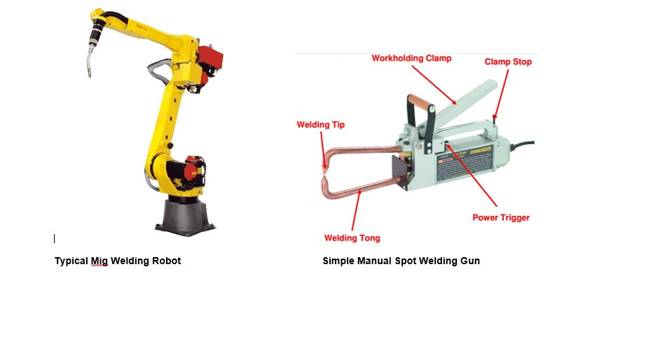
Situation: A stamping and welding plant consisting of 150000 square feet, 350 employees had a number of internal throughput bottlenecks which resulted in a delivery record of 97%. In automotive tier 1; the expected minimum metric is 99.99%. The plant contained 10 side frame presses ranging in size from 400 to 2000 tons. The majority of the presses were coil end fed but could be configured differently based on the product. The welding shop contained 50 robots with 25 performing mig welding and 25 units spot welding.
The plant suffered from the following problems:
Press shop up time of 18-25%. A well running press shop will run at 85 to 90% up time.
Excessively long change over times of up to two days. Keeping in mind that some shops change their presses in minutes, a 4 hour changeover for this shop would be considered acceptable.
An epidemic of smashed stamping dies which resulted in a tool room running chronically 100% over budget.
Weld shop rework in excess of 60% in an industry where 2% on a bad day is considered acceptable.
Sport utility gas tank protective cover robotic spot weld cell
Bumper mounting bracket weld cell
Shielding gas changeover
Tailgate spare tire mounting bracket weld cell
Car Bumper weld assembly cell
Seat belt anchor spot welder
Spot welder deformed welding tips
Mig welding process standardization
A chronic problem with an average of 10 cold welds per assembly.
A high level of downtime. The cell required the constant attendance of a robotics technician to clear low pressure faults and restart the cell.
2" main appliance shutoff ball valve,
Air receiver of size 3 feet diameter by 6 foot length,
2" main applicance compressed air pressure regulator,
1 1/4" branch pressure regulator installed on each zone,
1" individual pressure regulator at each spot welder pressure multiplier.
There were two problems with this arrangement:
The air receiver was installed up stream of the first regulator and should have been installed downstream of the first regulator. The first regulator is intended to buffer the robot cell from fluctuations in the plant air supply pressure. The receiver was moved to the downstream side of the 2" regulator.
There were two many regulators in the air delivery piping and as many orifices which acted as pressure restrictions in the air supply piping inside the cell. The zone regulators were removed.
Outcome: 1. A 90% reduction in pressure fluctuation on all gauges was observed when spot welders were engaged. 2. Pressure faults were eliminated. It was no longer necessary for a robotics technician to be present to keep the cell running. 3. Most importantly there were practically speaking, no more cold welds; Product quality in terms of nugget weld penetration was now excellent.
Manual load.
Fillet welding of the stiffener bracket by two robots.
Projection welding of the nuts.
Unload by robot to a bolt press insertion station followed by mechanical ejection after threaded stud installation.
An experienced welding industry consultant recommended that the welding process be converted to metal inert gas shielded arc welding using hard wire of the same gauge thickness. The flux core wire was deemed unnecessary and the cell should be converted to use a mig process with hard metal wire. Power supply voltages should be increased to achieve droplet transfer from globular transfer. Droplet transfer was considered to produce a far superior weld quality in the industry. A 13% carbon dioxide argon mix shielding gas was recommended. The plant was using a purported 9% mix. Note that carbon dioxide is used to create an exothermic weld puddle and a weld with good penetration. The specialist indicated that 9% mix produced lower penetration quality.
It was observed that none of the fixtures had jam nuts to secure and lock the fixturing positioning adjustments in both the x and y directions. The adjustment screws were quite loose. If the fixtures were moving, this would cause positioning problems with both the fillet welding and projection nut welding processes.
The cell was shut down for five days:
All four fixture stations were adjusted to present a consistent position of parts at the fillet weld station. Jam nuts were installed. The table was rotated to verify the part presentation consistency at the fillet welding station.
Bottled 13% shielding gas was installed at the cell to facilitate the test. Coils of hard wire were installed in the feeders.
Outcome:
Within days of making these changes, the cell was running at 750 pairs per shift.
Weld quality was very consistent, far superior and had excellent penetration. Note, during the changeover, the robotics technicians were not able to achieve acceptable weld penetration with the centrally piped 9% CO2 shielding gas and achieved good penetration when the cell was rigged with gas bottles containing 13% CO2/Argon blend shielding gas.
The cell was now running with less than 10% manual rework.
A 40% savings in weld wire consumable was realized.
Delivery performance on this component achieved a consistent 100% on time delivery to the downstream bumper final assembly weld cell.
3. Shielding gas changeover (common cause quality problem):
The process produced parts with a lot of cold welds. Often one cycle of a total four welds would have 3 cold welds. A cold weld is one which has no fusion and pulls apart with ease.
The process was running with an unusual level of weld expulsion. Weld expulsion is literally an explosion of liquid metal from the spot welding process. Employees' clothing would be full of holes after a shift. Employees were forced to wear special aprons and face shields to protect themselves from the constant expulsion. Nobody wanted to run this welder.
The welding machine required frequent robotic technician attention to adjust and re-secure proximity part presence sensors.
Part shipments to the end customer were chronically late.
Given the high level of cold welds, there was a high probability that this problem was being leaked to the end customer.
The root cause stumped all of the site staff. At one point in frustration, staff were in the process of organizing a completely manual off line spot welder.
After observing the welder run for a period of two hours, it appeared that the guns might be coming off the part early before the spot welds were completed. A spot welding process employs very high amperage currents of 25000 to 30000 amps for a very brief period of 6-10 hertz (1/10th of a second). If the low voltage high amperage current was still on as the welding tips pulled away from the part, an electric arc having a temperature of 20000 degrees celsius would be created. This would be more than enough to vapourize any metal grounding the arc. A great deal of expulsion would result.
A PLC programming specialist was engaged to examine the program. The following problems were found with the program:
There were no time delays between the completion of the weld cycle and the removal of the guns with the result that an arc could be pulled for a brief period.
The outputs used to control the air valves that lowered the weld guns were not latched once the limit circuit which included a variety of sensors was made. This allowed the guns to pull off the part if for example a part presence or table in position sensor fluttered. Given the frequency of loose sensors and the hourly need to tighten them to keep the welder running, this would also be the source of an even greater amount of expulsion. Further, the air over hydraulic spot weld guns clamped the stamping with tons of force to ensure intimate contact between the two parts to be welded. Together with the thermal stresses from the spot welding process this would result in warping of the sheet metal stampings and loss of contact with the part presence sensors. Any of these conditions would result in a gun pulling off the part during the spot welding process resulting in liquid metal expulsion from the arc created.
Actions:
The PLC programmer was asked to create a new program starting with a blank sheet of paper. This program would include process timers separating the start and stop of the spot welding power from part presence and machine motions (guns down and up etc.). Critical outputs would be latched to eliminate any chance of guns being withdrawn while the welding current was on.
Jam nuts were installed on all of the inductive proximity sensors on the fixturing.
Outcome:
The welder started up with a complete elimination of cold welds. In inspection, the parts pulled apart, with a consistent adhesion nugget being pulled out of the parent material indicating excellent and consistent adhesion.
There was a complete elimination of expulsion.
The part proceeded to run with 100% on time delivery.
7. Spot welder cold welds and deformed (mushroomed) copper tips (common cause quality problem):
Situation: The shop contained about 25 spot welding robots or guns in total. There was a daily common cause problem associated with cold welds occurring at seeming random.
Investigation: With many of the above crisis type problems addressed, focused attention could now be devoted to this problem. When such problems occurred it was common practice to change out the copper tip. Copper tips cost a few dollars each, are hollow for water cooling and are threaded for easy installation onto the tip of a spot welding water cooled copper electrode.
Inspection of 30 of the mushroomed tips removed from the process found that there was a thick layer of calcium on their insides. It was theorized that the calcium was increasing the resistance to heat transfer resulting in a hot tip which would mushroom after a relatively short term in service (a few shifts).
The spot welders received cooling water from a centralized cooling water distribution pipe system. A review of the water softener installed on the makeup line to the system indicated that the softener had probably not been in service for at least a decade.
Given that the plant was located in a city near the Niagara Escarpment and that the town got half of its water from artesian wells, a water treatment company was engaged to test the water in the city supply. A hardness of well in excess of 300 ppm (soft water <17 ppm) was found (off the meter's scale) was found.
A new water treatment system was installed. At the same time, the water treatment supplier was engaged to acid flush the system to the spot welders with sufficient acid to remove the calcium scale. This process took a full two days on a weekend involving over 20 hours of flushing before the re-circulation water pH started to drop. It was estimated that several hundred pounds of calcium sludge was collected in the welder point of use filters. Filter elements had to be changed several times before they stopped fouling during the first week of operation after acid flushing.
Outcome: There was an estimated 95% reduction in the incidence of mushroom tips with a corresponding reduction in cold weld frequency. Case examples one and six above are special cause problems. This case is an example of a common cause problem in a spot welding process.
Change the shielding gas to 13% carbon dioxide.
Standardize the weld material process to droplet mode from globular transfer. Set all power supply voltages to a standard setting to achieve this.
Set all other weld parameters such as stick-out distance, wire feed speed, shielding gas flow, and torch travel speed the same settings, needed to achieve acceptable single pass bead size, penetration and weld quality.
Outfit all cells with hard filler wire of size 0.030".
A marked improvement in visual mig weld quality was achieved having good penetration everywhere with very low levels of spatter.
The level of manual rework with hand held mig torches dropped from over 60% to under 10%.
A $40000 per month savings in weld shop consumables was realized.
The on time delivery record for the site moved to 100% consistently.
Internal scrap dropped to nil.
Premium freight of $70000 per month was saved.
The shop absorbed a 20% increase in sales without the need to hire anyone.
Bottom line profit almost doubled from 12 million to 23 million per year.
The general manager in trying to ensure a best in class welding shop had recruited a number of engineers with a welding major. In dealing with welding problems in this shop these individuals, with great pride, had tried to fix basic welding problems by changing the welding processes by for example, using bigger wire, more amperage, use of metal core wire and flux core wire and finally a less than optimal shielding gas. Further, the shielding gas, which was determined to be the most important variable in achieving good weld penetration, was not being routinely monitored. As a result the concentration had dropped to an extremely low level, resulting in poor or no penetration consistently. The result was a shop with a chronic rework level of over 60% and one which was failing to deliver on time.
All of the solutions implemented here were process related and did not require any prior welding knowledge.
