Aluminum casting foundry work cells case examples
Background: An aluminum jobbing foundry produced approximately 1000 different castings in several different alloys for over 300 customers. There were about 170 employees working in a total of four semi contiguous buildings of 80000 square feet total. It produced castings using a total of 15 primary processes as follows:
Sand moulding: Automatic Hunter machines (two sizes), jolt squeeze (two sizes), floor moulding with green sand and resin bonded sand.
Core making: Manual CO2 cold set, automatic cold set and hot box processes.
Permanent mould: semi-automatic tilt pour and manual vertical parted moulds
High pressure die cast machines: 300T 600T and 800T
It was losing money.
Quoted lead times for castings were over 6 months.
The foundry process was organized along functional lines.
The internal foundry discount rate averaged 50% and may have been as high as 75 to 80%.
It was in danger of being closed.
Implement cross functional work cells.
Reduce the number of primary processes from 15 to nine by undertaking the projects below.
Convert all jolt squeeze moulding processes to the Hunter automatic moulding machines
Convert all hot box and manual coldbox CO2 core making process to high speed Lampe could box moulding process.
Achieve a target pouring yield of 60% on all processes. The base level pouring yield was thought to be less than 35%.
Undertake a program to get the cost of quality from 75% to under 10%.
Reduce the floor print by 50%.
Reduce the labour complement by at least 50%.
The following work cells setup to improve productivity:
Relocation of cutoff band saws.
Automated moulding system cell
71/4" circular saw blade case and safety cover finishing cell.
1. Band saw relocation:
Situation: Previous management to make the site more efficient had created a department for every operation. e.g. Core knockout department, the cutoff department the core making department and so on. This created lots of material handling, lots of storage, lost inventory and big increases in lead time. Often due to misplaced parts, items were moulded twice at great expense.
Analysis: A mechanic suggested that the band saws be moved back to each moulding station. With approval to do this given, a few hours later he and his coworkers and moved several band saws back into the various moulding departments.
A band saw was placed beside each permanent mould casting station. The cycle time for this process was 2-3 minutes. It took the operator only 30 seconds to open th emould, extract the casting, close the mould and pour the next casting. This resulted in 1.5 to 2 minutes of idle time. Since it only takes less than 10 seconds to cut the sprue off the casting it was now possible for the operator to mould and cutoff the casting instead of just mould the casting. Cutoff was now free. Hot sprue could be put back into the furnace. The operator was provided with appropriate heat and cut resistant kevlar gloves.
A bandsaw was placed near the end of the gravity roller conveyors in the manual sand foundry. The labourer shaking out the moulds now cut off and placed the various castings into separate baskets.
A third bandsaw was placed at the end of the Hunter moulding line.
Outcome: After overcoming the initial resistance of the affected employees to this change (their percentage of work in a cycle was now more than it was previously) the following benefits were reaped:
There was a 75% drop in lifttruck propane consumption plant wide suggesting that material handling had dropped by 75%.
There was an 80% drop in sprue inventory. Operators were melting the sprue (gating systems) as they were cutting the splashes from the moulds and putting the sprue back in the furnace.
Since castings from the sprue take up a fraction of the volume of the splashes which contain sprue and casting, there was a 90% drop in material handling associated with product where a saw had been relocated.
The plant employed a total of 11 lift truck drivers prior to the change. Layoff notices were issued to seven drivers saving $280000 per annum.
There was a $500,000 reduction in working capital needed to run the business associated with reductions in raw material and in process inventory.
Lead times were cut substantially by linking moulding and cutoff processes together.
2. Automatic moulding system work cell improvements:
Situation: A
 green sand moulding system consisting of two automatic Hunter moulding machines, a green sand mixing and conveying system, green sand mould roller belt conveyors, a poured mould shakeout, sand return system and three 1000 pound natural gas fired pot furnaces manned by three employees made castings at the rate of 40 to 120 moulds per hour.
The location of core making and downstream processes in other buildings was creating excessive material handling.
Lead times were excessive due to the need to material handle and store product at each of remote processing stations. There was excessive and unnecessary repetitive pick and place labour.
Core making issues: With the cold box Laempe sand core machine in a separate building, a lift truck had to transport them outside over rough concrete driveway causing lots of breakage. If it was raining, even small amounts of water falling on the cores would expand 1000 times inside the mould with the pouring of liquid metal causing lots of scrap. The employees were putting extra resin in the sand to make them stronger to withstand the rough material handling. Core knockout times were 3-4 times higher as a result. In some cases employees used manual pneumatic chisels to break the core by hand out of the castings.
A decision was made to relocate, core making, core shakeout, cutoff shot blast and profile grinding processes into the same building proximate to the moulding line.
The equipment involved is shown in the graphic below.
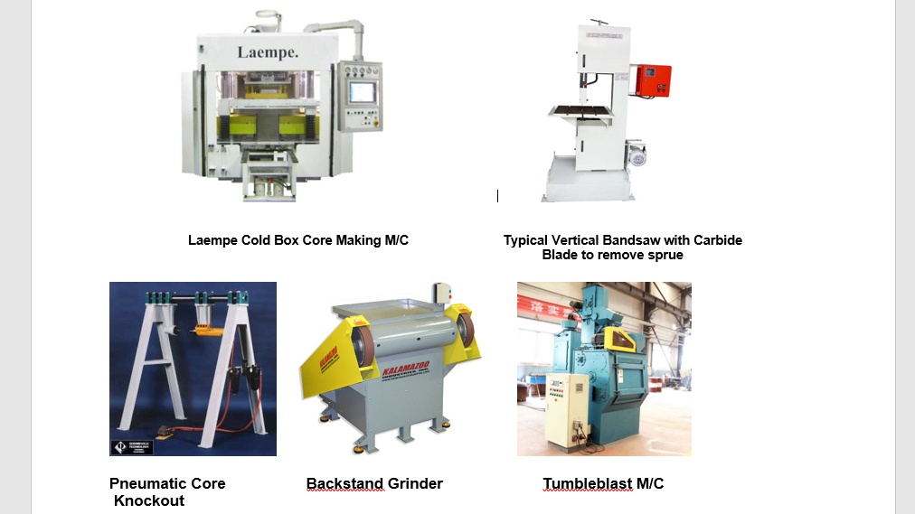
Actions:
A contractor was hired to disconnect, relocate and reconnect the Laempe core machine to a spot at the moulding machine end of the shop. Cores were now inventoried on the floor near where they were set in the moulds. A simple hand pump pallet truck could be used by the moulding machine operator to move the cores to the setting station. A scissors lift was procured which allowed the Hunter machine operator to ergonomically raise the cores to an appropriate height.
A band saw was relocated to the shakeout end of the line. A simple shelf/box was fabricated to the left side of the band saw to place the saleable castings after cutoff. A spot was painted on the floor to the immediate right of the saw for a sprue material handling wire basket.
The pneumatic core knockout was outfitted with two hand press button cycle actuators. The machine was located to the immediate left of the mould shakeout.
Further to the left of the core knockout was located the tumble blast shot blast machine.
In front of the shot blast machine and about three feet from the band saw casting shelf was a relocated back stand belt grinder.
Interlocking schedules for core making, metal melting and moulding were created together with a daily pick and deliver list for core boxes and match plates etcetera.
Tooling changeover conversion processes and procedures were created to allow technicians in the tool room to convert 1. jolt squeeze match plates to the Hunter process, and 2. hot box coreboxes to the Laempe process.
The line was now run with, five employees with one employee making cores, a second running the Hunter moulding machine, a third pouring the metal, a fourth doing mould shakeout, core shakeout and cutoff and a fifth employee doing flash and gate grinding and tumble shot blast.
This new layout allowed the site to produce castings in less than 5 business days, including heat treatment and order entry.
There was a 90% reduction in material handling.
There was a more than 50% reduction in raw material, work in process and finished goods inventory with a corresponding reduction in working capital.
Core breakage associated with outdoor material handling was eliminated together with water evaporation defects from rained on wet cores in the moulds.
A host of pick and place ergonomic issues were eliminated.
The hot box core making shop was shut down and the equipment sold.
A number of back stand grinders were no longer needed and were redeployed or sold.
A number of pot melting furnaces in the jolt squeeze shop were surplus, shutdown, disconnected and sold.
All castings made on this line became far more profitable to produce.
At least seven other employees were no longer needed at an annual cost savings of 250k per year.
Several thousand square feet of floor space was freed up for redeployment.
Foundry capacity to produce green sand aluminum castings more than quadrupled.
Castings contained unacceptable levels of small porosity voids on the parting lines of the blade case and safety cover.
The blade case and safety covers were warped and damaged and did not fit their machining fixtures consistently and therefore could not be used.
The colour of the castings varied from box to box and with in a box forcing them to employ two employees to colour match the castings in sets prior to assembly.
The customer indicated that the return level of 80% was causing them to incur substantial extra costs. However they were more concerned about the financial viability of the foundry as a supplier given the ongoing high level of returns which averaged 80%.
Analysis:
The die cast plant use high pressure presses sizes to shoot and cast the castings. This process was deemed to be operating with low end of stroke squeeze pressure.
Due to the thin gating systems on all three castings, breakoff was completed manually by employees without difficulty.
After break off employees carefully grounded the gates flush to each casting using a back stand grinder with a 60 grit belt. Some skill was needed to avoid excess grinding of the gates and scrap.
After flash grinding, spacer supports (special internally cast castings) were inserted in the blade case and safety covers to provide support during the shot blast process. The castings were shot blasted in a tumble blast machine loaded with stainless steel cut wire media. The cycle time was only 30 seconds. Castings were sustaining a high level of warpage and mechanical damage in this process.
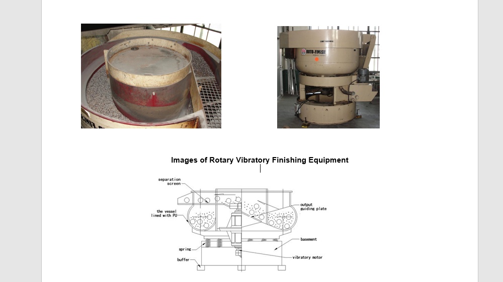
After shot blasting the support inserts were removed and the castings were placed in a rotofinish vibratory parts finishing machine loaded with carbon steel media. After this process the parts were observed to have a variety of different hues. This machine used a soap water solution. The metering and addition of the soap to the machine was not very well controlled due to the lack of pressure regulation of the water supply from the city and manual controls on the soap flow. Further, at night when the machine was not being used, the media would rust. In the morning when the process was started, the water would become stained with rust for the first few hours. During the day as the rust concentration abated to zero, the colour of the finished product would change accordingly. Images of typical vibratory finishing process are shown below.
Finally the parts are packed in wire mesh shipping containers with cardboard tier spacers and liners to prevent damage.
Action Items:
To resolve internal porosity with the die castings, the end of shot high pressure squeeze pressure was increased substantially. Process setup cards were completed to ensure setups were repeatable.
To improve fit and support issues with the spacers, the patterns were modified a number of times and tested until a better more consistent outcome was realized.
A control was put in place to automatically make replacement sets of spacers every four months to address the wear problem with repetitive shot blast cycles.
After consulting with the supplier of the media to obtain a less aggressive media, round metal bead was substituted and the cycle time was increased to two minutes. Stainless steel cut wire media was identified has the one of the most aggressive shot medias which could be used and certainly should never have been used to clean aluminum castings. The new media peened the surface, and did not open any near sub surface porosity pores while still producing a consistent finish on the parts. To resolve issues with rusting of the media, a procedure was put in place to run the machine for 15 minutes prior to use with dummy parts to clean the media of iron oxide rust.
The vibratory finishing machine which was prone to failure (motor and vibrating weight falling off) was given a major welding repair which added numerous gussets to the tub stucture and fixed an assortment of large fatigue cracks. A PLC controlled control panel with mixing proportional flow controls for the soap and water was added. This locked the ratio of soap to water. The machine started automatically and ran for 15 minutes every 4 hours to churn the medium and scrub any new rust from the tub.
A small cell was setup with a back stand grinder, the tumble blast machine and the vibratory finisher. One employee ran the cell performing, break off, flash grind, shot blast vibratory finishing and packaging.
Customer returns dropped from 80% to under 0.3% and stayed there for three years running.
The OEM customer indicated that this foundry was now their best supplier world wide out of 30 countries.
Labour to process this product dropped by more than 90%, 80% drop due to the 80% returns and the need to make the parts four times and another 50% for the savings associated with the cell.
The product became profitable to manufacture.
